Published
JANOG51 NETCON Walkthrough (Level 1-4): Troubleshooting RIP
Combine static routes and RIP redistribution to restore connectivity from Osaka-B, including its loopback interface, to Tokyo-A.
Contents
This post publishes the JANOG51 NETCON level 1-4 walkthrough on behalf of its author, 村久木. Thank you for creating the challenge.
The explanation below is from the challenge author.
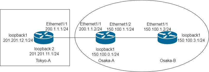
Topology
Problem statement
You are a network engineer at a company with its headquarters in Osaka and a branch office in Tokyo.
Osaka-A’s Ethernet1/1 can communicate with Tokyo-A’s Ethernet1/1, and Osaka-A’s Ethernet1/2 can communicate with Osaka-B’s Ethernet1/1. However, Osaka-B’s Ethernet1/1 cannot communicate with Tokyo-A’s Ethernet1/1.
The Osaka routers use RIP. Connectivity to Tokyo must use a different method. Enable communication from Osaka-B to Tokyo-A.
Goal
Pings from each interface on Osaka-B must succeed to:
200.1.1.1201.201.11.1201.201.12.1
Restrictions
- Do not configure
200.1.1.1/24as Osaka-B’s default gateway. - Do not configure RIP on Tokyo-A.
- Do not add IP addresses to loopback interfaces.
Walkthrough
Thank you to everyone who participated in JANOG51 NETCON. This was my first time creating a challenge through the program for new challenge authors.
Issues
There are two problems:
- Incomplete routing configuration prevents Osaka-B and Tokyo-A from learning routes to each other.
- Tokyo-A lacks a route to Osaka-B’s Loopback1, so communication using that source interface fails.
Expected solution
The expected solution combines the following changes:
- Configure static routes, a route-map, and redistribution of static routes into RIP on Osaka-A.
- Configure a static route on Tokyo-A.
- Enable RIP on Osaka-B’s Loopback1.
Scoring
| Score | Requirement |
|---|---|
| 50% | Osaka-B’s Ethernet1/1 can communicate with Tokyo-A |
| 100% | Both Ethernet1/1 and Loopback1 on Osaka-B can communicate with Tokyo-A |
Configuration steps
On Osaka-A, add static routes to Tokyo-A’s Loopback1 and Loopback2 networks. Use Tokyo-A’s Ethernet1/1 address as the next hop.
Osaka-A#configure terminal
Osaka-A(config)# ip route 201.201.11.0 255.255.255.0 200.1.1.1
Osaka-A(config)# ip route 201.201.12.0 255.255.255.0 200.1.1.1
On Tokyo-A, add the return route to the Osaka networks via Osaka-A’s Ethernet1/1 address.
Tokyo-A#configure terminal
Tokyo-A(config)# ip route 150.100.0.0 255.255.0.0 200.1.1.2
Create a route-map named netcon on Osaka-A. A permit entry without a match condition allows the static routes being redistributed.
Osaka-A#configure terminal
Osaka-A(config)# route-map netcon permit
Redistribute the static routes into the RIP instance used within Osaka.
Osaka-A(config)#router rip 0
Osaka-A(config-router)# address-family ipv4 unicast
Osaka-A(config-router-af)# redistribute static route-map netcon
At this point, Osaka-B’s Ethernet1/1 can reach Tokyo-A, meeting the 50% scoring requirement.
The Osaka routers use rip 0, where 0 is the instance tag. Enable RIP on Osaka-B’s Loopback1 to advertise its route and allow communication from all of Osaka-B’s interfaces.
Osaka-B#configure terminal
Osaka-B(config)# int loopback1
Osaka-B(config-if)# ip router rip 0
Verify connectivity using both the default source and Loopback1.
Osaka-B#ping 200.1.1.1
Osaka-B#ping 201.201.12.1
Osaka-B#ping 201.201.11.1
Osaka-B#ping 200.1.1.1 source-interface loopback1
Osaka-B#ping 201.201.12.1 source-interface loopback1
Osaka-B#ping 201.201.11.1 source-interface loopback1
Closing thoughts
Seeing solutions beyond the expected answer was a valuable learning experience. Thank you to everyone who participated.